Cruise Checklists: What If, Why, and When

By Markus Rex

All of us who do frequent long cross-country flying sit in the airplane, comfortably, being carried to our destination, with the engine humming along nicely, and lots of complex machinery doing its part in getting us there. If you are like me, you occasionally think “it would be good to think about what-if”. We all should, but hundreds of hours of safe flying are doing their part and add to our complacency. If we are instrument rated, we even have ATC watching out for us – great!

Yet sometimes the small voice becomes loud enough to do something about the “what if” question. For me it happened during a long solo cross-country flight in night IMC, when each flicker of a needle is analyzed, the engines are watched constantly and every ever-so-slightly changed sound gets the adrenaline going. After that flight, I thought it would be good if I kept similar vigil during flights under more relaxed conditions (Day VFR on an IFR flight plan comes to mind). After some pondering I adapted the airlines’ idea of regular structured instr
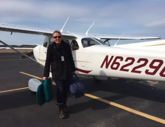
ument checks during cruise for my GA flying. My “Cruise Checklist” was born. 

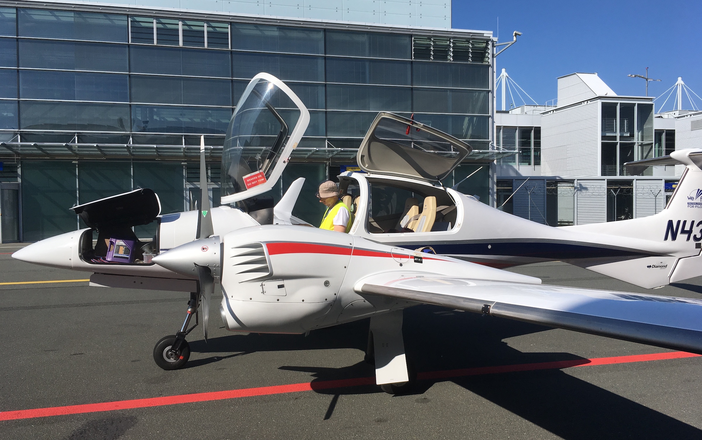
My wife Heidi is also a pilot, and we do most of our flying together. So on the next few flights we experimented with the concept, and came up with a good flow (all our checklists are flow-based) that works for us. Below are the variants for a Cessna 172S with a G1000, and a fully equipped Diamond DA42 twin:


Cessna:

Diamond:

Initially we had more specific tasks outlined, but quickly settled on generics, to combat the complacency and force mental agility. The pilot still needs to have the full picture in his or her head – for example how much fuel is expected in the tanks, taking the time since the last check and the fuel flow into account. Or understand which are safe engine operation parameters. That big picture might just be enough to help you out of a bind when an emergency happens.

Another part of our experimenting was the frequency for the cruise checklist. As it is intended as a back-stop to prevent any aspect from being overlooked during the regular PIC watch duty, it makes no sense to run it every 5 minutes. And once an hour might be great on a transoceanic flight, but not really helpful in a Cessna 172… we settled on every 15 minutes as our optimal timing. 

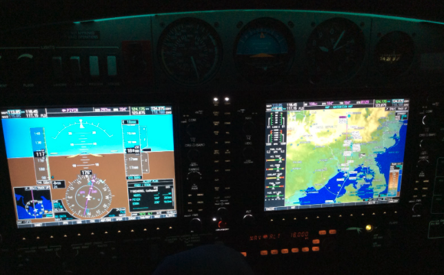
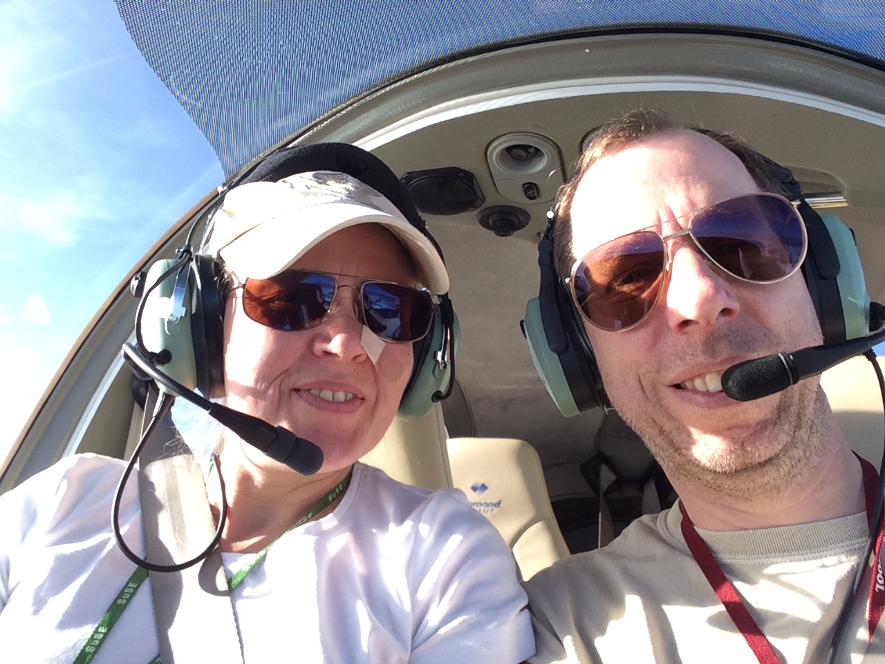
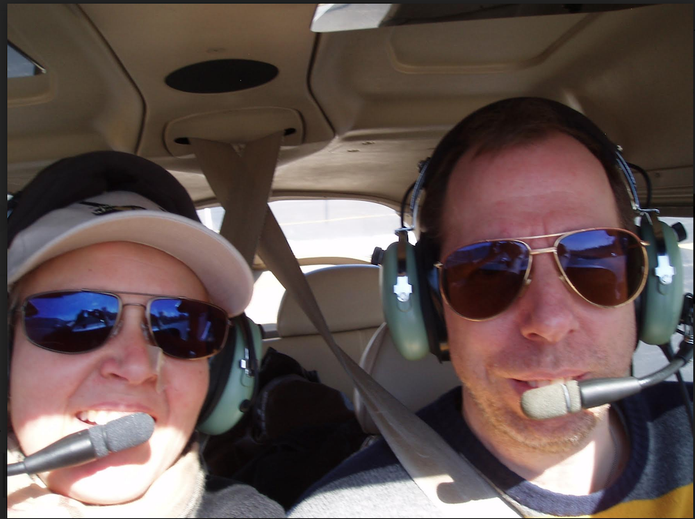
[In this picture, we are cruising along at night, high above a thick layer of clouds, with the next waypoint being over 90 min away. GREAT time to lose vigilance without a constant reminder like the cruise checklist.]

During the optimization phase we discovered that running the cruise checklist every 15 minutes after reaching cruise altitude adds a lot of distraction and unreliability. We now run it at XX:00, XX:15, XX:30 and XX:45, starting with reaching cruise altitude. So if we reach our cruising altitude at 09:37, we run the cruise checklist the first time at 09:45, the second time at 10:00 and so on.

Running the cruise checklist regularly does not make the small voice at the back of my mind go away, alone in the dark and the clouds, but it gives me a framework and a reassuring back-stop of tasks completed, and ensures that we do not lose the big picture, while still listening to every faint engine noise change.


Markus and his wife, Heidi, split their time between Germany and Boston. They own and fly a DA42.


NEW: Flight Path Vector in 3D Cockpit/HUD

We’ve released a new feature in 3D cockpit view – a Flight Path Vector (FPV) display.

The Flight Path Vector as shown in CloudAhoy mimics the display of an aircraft’s avionics during flight. It shows the path the plane is flying, which may be different from the heading. 

   
Flight Path Vector in flight                         Flight Path Vector in CloudAhoy debrief (computed) 


Debriefing with Flight Path Vector

The Flight Path Vector is a powerful tool for debriefing:

  • Approach / aiming point: was my aiming point on the runway where I wanted it?
  • Wind correction e.g. crabbing: did I over correct or not put in enough correction?
  • Straight and level flight: how well did I maintain altitude?
  • Level turns: did I climb/descend during the turn?

Initially used in the heads up display (HUD) of fighter aircraft, the Flight Path Vector (also called the flight path marker or velocity vector) is now an industry standard used by Garmin, Avidyne, Rockwell Collins, X-Plane and others. The Flight Path Vector can be found in most modern primary flight displays (PFD) and as a key feature of glass cockpit synthetic vision. The Flight Path Vector provides situational awareness for professional, military, and general aviation pilots. 


Examples

  • Approach / aiming point 

Below, the FPV indicates that the pilot had a nice aimpoint at the beginning of the runway. A Flight Path Vector fixed to an aimpoint on the runway, not bouncing around is often a good indicator of a stabilized approach and landing.


  • Wind correction e.g. crabbing 

In this example, the aircraft is facing a strong crosswind from the right. The nose of the aircraft is pointed to the right, crabbing into the wind. The FPV is lined up nicely with the runway centerline, indicating that the wind correction angle is correctly applied. 


  • Maintaining altitude in slow flight 

Here we debrief a slow flight, just as the stall is imminent. This flight path angle shows how even though the attitude of the aircraft is pitched up, the Flight Path Vector is below the white horizon line and indicating that the aircraft is actually descending, unable to maintain level flight as it reaches a stall.


How does CloudAhoy create the Flight Path Vector?

CloudAhoy creates it using GPS position data. To compute the FPV during animation, CloudAhoy connects a line between a previous and current position of the aircraft, and extends it forward. Extending it all the way to the ground shows where the aircraft would be if it continued its current trajectory, and that point is where the FPV symbol is placed. If the aircraft is climbing we place the FPV symbol above the horizon at an imaginary point where the aircraft would be if its trajectory continues.

F-18 pilots, landing on an aircraft carrier, depend on their Flight Path Vector. Yet, it is a powerful debriefing tool even for $100 hamburger sorties, even if you fly a 6-pack avionics aircraft. 

The Flight Path Vector was added as part of working with Embry-Riddle faculty, per their suggestion and request. The Flight Path Vector is available for Standard and Pro users.

Debriefing Circling Approaches with CloudAhoy – Major Improvements!

IFR students do not like to practice them.
. . . Airlines pilots are typically not allowed to fly them.
. . . . . . And the FAA considers eliminating them.

Yet, flying a circling approach is an essential skill that every instrument pilot must be proficient in. CloudAhoy can help you debrief the circling approach.

CloudAhoy’s analyzer automatically identifies circling approaches.

ILS approach to RWY 03, which ended in a circling to runway 21. The  published KOGD ILS RWY 03 in magenta. The actual flight’s path is shown in peach color; the pilot followed the glidepath, then deviated from it for the circling maneuver. Airspeed and Altitude are shown on the graph.

CloudAhoy Pro breaks the entire instrument approach into its different subsegments. The last sub-segment of a circling approach is labeled “circling”.  It also scores the circling approach.

The one-minute debrief
Many times, a one-minute debrief in CloudAhoy is all it takes to evaluate the circling maneuver. You look at the altitude and airspeed profile, the maneuver’s shape, and your score.

Expand the score to see the details.
Notice that three of the scoring criteria are related to circling; they are highlighted in the screenshot below:

  • TRK at THLD: we check that the aircraft is aligned with the runway at the threshold. No “cutting the corner”.
  • Circling speed: we verify that the circling speed is within the recommended range.
  • Circling within the protected area: per the aircraft category and the MDA.

We also relaxed some of the stabilized approach criteria, for example we don’t score AGL over threshold like we do in a straight-in approach.

Questions you may want to ask, and answers from the debrief of the flight shown above:

  • General safety of the circling – what were the altitudes (MSL, AGL) and the airspeed? How consistent were they?
    –> Answer: in this circling approach, consistent 1000′ AGL, and 120 KIAS.
  • What was the shape of the circling part and the distance from the airport?
    –> Answer: most was well inside the 1.9 nm radius for this aircraft category, but the actual circling started 2.4 miles before the runway, thus receiving zero score for this item.

The 3-minute debrief

Note the annotations, under the graph, of the sub-segments of this approach: flying from the IF to the FAF • from the FAF to the beginning of the circling • the “Circling to RWY 21” maneuver.

The airspeed was about 120 KIAS during the circling. The blue rectangle represents the recommended circling speed. The altitude was ~1000′ AGL.

>>>> We can dive in for details about the Circling part: <<<<

The Segment Manager includes an RNAV segment. Note the “CIRCLING RWY 21” text in the segment:

Open the segment (click the black triangle) to show its subsegments:

Looking at the flight parameters (lower-left), you can see the AGL as you play the flight or scrub through the graph.


You can look into more details about your circling area and distance to the runway by opening the “CIRCLING” graph from the Segment Information. This graph will show you the minimum distance to all the runways during the circling.The green rectangle helps to visualize the 1.9 nm protected circling area for this aircraft (a citation jet). The pink area represents being outside of the protected area while circling. Note the position of the aircraft when it was 1.9 miles from the nearest runway; the circling started a bit too early in this case.

In the image below (a different flight), the circling area for the aircraft was 1.8 nm. As the pilot turns left towards the final approach, they exceed 1.8 nm away from the runway; we’ve highlighted this exceedance in pink so the pilot can see where this occurred.

Lastly, you may want to verify the max bank angle during the circling. You can either animate and look at the cockpit view, or, for better accuracy, declutter and display the bank graph (accessed from the left tools pane) for the circling sub-segment:


Our work on identifying and scoring instrument approach was driven by users’ feedback.
Please send us feedback that will allow us to improve our flight analyzer


Flying “The Gauntlet”

This flight route was from San Carlos airport down to Reid-Hillview airport, just southeast of San Jose, and back. The flight was fun and the fact that my flying club affectionately calls this flight route “The Gauntlet” only made it more of a cool thing to do.

The challenge of The Gauntlet is that in just 30 miles you encounter boundaries and shelves of Bravo, Charlie, and Delta airspace and must talk to San Carlos tower, Palo Alto tower, Moffett tower, San Jose Tower, and finally Reid-Hillview tower (and all over again to get back home). 

This flight certainly requires planning and advance preparation. I was sure to write down all frequencies on my knee board before arriving at the airport, as there was no way I wanted to scramble to find them on a chart or try to write down a frequency from fast talking air traffic control in flight. It was also important to discuss altitude considerations and expectations before departure. Getting oriented with Reid-Hillview airport in advance was helpful to make sure I was ready for an approach to parallel runways, a displaced threshold, runway length (decision: I will land and taxi back vs. attempt touch and go’s), a short taxiway between the runways, and noise abatement procedures.

Thankfully my flight over to RHV was pretty smooth, the controllers gave me the handoffs as expected and I didn’t have to worry about getting too close to the next boundary without talking to the correct controller. My instructor told me to expect to cross SJC at exactly mid-field, so you can see me head more south to make sure that crossing was spot on, but they ended up clearing me direct to RHV anyway.

It has been a while since I have flown into an airport with parallel runways and I was obviously a bit intimidated by it and the parallel traffic, because you can see that I turn way too early for my final on the first landing, but I fixed it the next two times around.

To complete my debrief, I used the view lock function to line up and compare the scores of my four landing approaches. I’m happy to see three of the four have similar total scores in the green. But, as I’ve seen in previous debriefs… I still always earn my lowest scores on centerline deviation. So, this is something I probably need to practice more and bring up to my instructor when I fly with her. 

This flight is on the syllabus for the private pilot students at San Carlos Flight Center. When you complete the flight and all of the radio calls, you are awarded “The Gauntlet” pin of achievement. I think it is great that SCFC includes fun milestones like this in training. Even though I’m not in private pilot training, I found that this flight exercise was great for a former rusty pilot to fly to keep honing her skills and working that brain muscle.

For me, the flight had the perfect amount of challenge and total brain saturation, but I still felt like I was in the airplane the entire way and not letting it get ahead of me. During my debrief with my instructor, I said out loud, “That flight was really fun! I was on my toes the whole time and I loved it. It felt good to be challenged, but never overwhelmed into despair.”  

Debriefing an ILS Approach – Improved

What makes an ILS approach a good one? The simple answer is – staying on the needle…
And how to score it? Well, that’s not a simple matter. 

We made significant improvements to the scoring and to the visualization – so with a glance you can see immediately how good your ILS approach was.

At a Glance – The 1 Minute Debrief

Take a look at the ALT profile view and your overall score. Compare how closely your altitude track follows the solid black line of the glide slope and note that you’ve stayed within the bounds of the glideslope beam (the dotted black lines).

+ We’ve just added the glide slope beam to the ALT segment information graph. Now it looks a lot like the profile view we are all used to!

The 8 Minute Debrief

Using the Cockpit View you can animate and see the CDI. 

CloudAhoy computes “synthetic” CDI deflections (also new in this release). Of course if data is being imported from an EFIS such as a G1000, the CDI will be taken from the avionics rather than being computed.  

Scoring

We also enhanced the way the score is computed:  the scoring now takes into account glideslope & localizer accuracy, which makes the overall scoring more accurate. 

A good way to go deeper is to  take a look at what makes the score. How accurately did you track the localizer and glideslope? If you score well in those two areas, you likely flew a stabilized and consistent approach; good work. If you didn’t score well, take a look at the rest of the score details for more insight.

Then, scroll down though the segment information; expand to see graphs of how accurate the glide slope is and see the horizontal and vertical CDI tracking. The shaded green area represents the goal range of + or – one dot (1/2 scale deflection).  

Understanding an ILS approach with full situational awareness will help any level pilot fly the next one better and more precisely.

* * *

Available in CloudAhoy Pro.

These recents improvements were inspired by users’ feedback (thank you).  Your feedback is always welcome, and is an important contribution to the on-going enhancements to the analysis and visualization.  


Integration with MyFlightTrain by MyFlightSolutions

If the flight data is uploaded into CloudAhoy automatically from the airplane – how do we know who the pilot was?  Specifically, in a flight school – how do we know who the student and instructor were? 


Get pilots’ names from the scheduling program


We just completed integration with the scheduling program of MyFlightTrain by MyFlightSolutions.

When new flight data is uploaded to CloudAhoy, it calls MyFlightTrain, which retrieves the names of the Student and Instructor based on the tail number and the time of the flight.

  • This integration is available in MyFlightTrain Version 8 Release 5. 
  • It is available to any organization who is using MyFlightSolutions and CloudAhoy. 

Full solution: Automatically log flights
& put them in pilot’s account

Flight schools and individuals are increasingly adopting solutions to automatically upload data to CloudAhoy after a flight. This is an excellent way to free up pilots from doing extra tasks and clicks, and to guarantee that all flights are properly logged.

The integration with the flight schedule is a critical step in the full solution – have the flight ready to debrief without any action by the pilot.

Equipment

  • Equipment is installed in the airplane for flight logging and transmitting

See also: AirSync for automatic upload of G1000 flight data

For each flight – 

  • Automatically – logging of the flight data starts
  • Automatically – flight data is uploaded into CloudAhoy
  • Automatically – CloudAhoy retrieves the names of the pilots from the schedule app based on tail# and time of the flight

All this is done behind the scenes, automagically.

Debrief immediately after landing


After landing…

– The flight is ready for debrief in the pilots’ account, seconds after landing


* * *

Integration with other applications in the aviation ecosystem is vital for a good and productive user experience, and we continue to pursue that.